Introduction
I ordered an FT232RL USB To Serial Adapter Module and an Arduino Pro Mini (Atmega328 3.3V 8MHz) in a kit for $7 and an ESP8266 Serial Wifi Module for $3.21 in the hope of getting a Wifi capable small Arduino for as cheap as $10. I got those modules last week and already wrote a post about the Arduino Pro Mini, and now I got the wifi module also working.
Communicating with ESP8266 Wifi module directly (with gtkterm)
Wiring
I connected the ESP8266 with the FT232RL USB To Serial module accortding to the following description: http://rayshobby.net/?p=9734 . The pinout of the module:
"Connect the top two pins (UTXD, GND) and bottom two pins (VCC, URXD) to the RXD, GND, VCC, TXD pins of a microcontroller. Note that VCC must be no more than 3.6V. The middle four pins are should be pulled up to VCC for normal operation. However, if you need to upgrade the firmware of the module, you need to pull the GPIO0 pin to ground — that way upon booting ESP8266 will wait for a new firmware to be uploaded through serial. This is how you can upgrade the firmware in the future." (Source of the pinout and text: http://rayshobby.net/?p=9734 )
Communicating using gtkterm
After the physical connection it took me a while to figure out how to communicate with the module. First of all it can be called with AT codes (nice collection here: https://nurdspace.nl/ESP8266#AT_Commands), so I just needed to send those commands to the module in serial port. I am using Ubuntu, so I found gtkterm as a program for serial communication. After installing it with sudo apt-get install gtkterm and looking in the manual I thought it would be easy. I found out the serial port number for FT232RL using an ls /dev/ before and after connecting the device, and found the port /dev/serial/by-id/usb-FTDI_FT232R_USB_UART_A9M55VZZ-if00-port0. I also needed the baudrate of the communication. I found on many websites that it is 115200 or 57600, but mine was using 9600 (took me a while to figure out). So the final command for gtkterm was this:
gtkterm -p /dev/serial/by-id/usb-FTDI_FT232R_USB_UART_A9M55VZZ-if00-port0 -s 9600
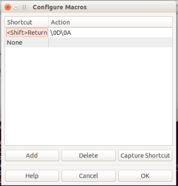
After entering this command gtkterm should open in a different window. But there is a problem: ESP8266 and gtkterm use different end-of-line characters, so I got no respond after typing in any command and pressing enter. The solution was to define a macro for Shift+Enter, which would send the text \0D\0A, which is equal to \r\n:
After defining this macro the AT commands worked like charm, I only needed to press Shift+Enter in the end of every command. I could list the available wifi networks, connects to the chosen one and so on. Nice description was found here: http://www.electrodragon.com/w/Wi07c#Steps_and_note
Updating firmware
First of all this action requires to change the wiring and connect GPIO0 pin to ground. I used the esptool.py software (can be downloaded from here) and the newest firmware for ESP8266 from here. The command was figured out using the readme file of esptool.py on its github page:
./esptool.py -p /dev/serial/by-id/usb-FTDI_FT232R_USB_UART_A9M55VZZ-if00-port0 write_flash 0x000000 v0.9.2.2ATFirmware.bin
It took a while to update the firmware but worked without a problem.Using with Arduino
First of all the ESP8266 works on 3.3V so a normal Arduino with 5V logic will destroy it. That's why I used an Arduino Mini Pro with 3.3V logic. The usage is not too hard, basically just like a normal serial communication. The Arduino sends AT commands and receives the same responses as we did with direct connection.
Using this intructable I wrote a program to send the analog value of port A0 to ThingSpeak.com in every 5 second. It was pretty straight forward using the instructable, so I won't write to much about it.
Wiring
The code
#define SSID "my_wifi_ssid"
#define PASS "my_wifi_password"
#define IP "184.106.153.149" // thingspeak.com
String GET = "GET /update?key=[THINGSPEAK_KEY]&field1=";
void setup()
{
Serial.begin(9600);
Serial.println("AT");
delay(5000);
if(Serial.find("OK")){
connectWiFi();
}
}
void loop(){
String a=String(analogRead(A0));
update(a);
delay(5000);
}
void update(String analog){
String cmd = "AT+CIPSTART=\"TCP\",\"";
cmd += IP;
cmd += "\",80";
Serial.println(cmd);
delay(2000);
if(Serial.find("Error")){
return;
}
cmd = GET;
cmd += analog;
cmd += "\r\n";
Serial.print("AT+CIPSEND=");
Serial.println(cmd.length());
if(Serial.find(">")){
Serial.print(cmd);
}else{
Serial.println("AT+CIPCLOSE");
}
}
boolean connectWiFi(){
Serial.println("AT+CWMODE=1");
delay(2000);
String cmd="AT+CWJAP=\"";
cmd+=SSID;
cmd+="\",\"";
cmd+=PASS;
cmd+="\"";
Serial.println(cmd);
delay(5000);
if(Serial.find("OK")){
return true;
}else{
return false;
}
}
Result
It was working as it intended to:
Controlling the Arduino from the web
So I was be able to send data to a website. Would it be possible, to do it in the opposite direction and turn on and off an led from a website? I started to do this, and after the Arduino send the GET command it receives the website sourcecode, but also the header of the site, like i found here:
AT+CIPSEND=0,47

>
 GET / HTTP/1.1
Host: retro.hackaday.com:80


busy

busy

SEND OK


+IPD,0,1024:HTTP/1.1 200 OK
Server: nginx/1.6.2
Date: Fri, 26 Sep 2014 20:27:11 GMT
Content-Type: text/html
Content-Length: 13258
Connection: keep-alive
Last-Modified: Fri, 26 Sep 2014 20:00:10 GMT
Accept-Ranges: bytes

<html>
<head>
<title>Hack a day</title>
</head>
<body>
code of the site
</body>
</html>
First I thought I would only get the sourcecode, and wrote my software that way, but that didn't work because of the header, and I haven't got time yet to fix it, so I will do that later.
Conclusion
For $10 I got a working Arduino with a wifi module, capable to connect to wifi networks and open webpages, which is amazing and I can't wait to use it in a real (useful) project like a lasertag system or some sort of home automation.
Best regards and merry Christmas:
Mark


