July 12, 2016

ESP8266 and beacon frames

In a previous post I mentioned a hack by kripthor about sending fake beacon frames with the ESP8266. The original code was limited to fixed 6 character long SSIDs and I wanted to extend it to arbitrary length.

Understanding the beacon frame

So the original code was sending this frame:

uint8_t packet[128] = { 0x80, 0x00, 0x00, 0x00,
/*4*/ 0xff, 0xff, 0xff, 0xff, 0xff, 0xff,
/*10*/ 0x01, 0x02, 0x03, 0x04, 0x05, 0x06,
/*16*/ 0x01, 0x02, 0x03, 0x04, 0x05, 0x06,
/*22*/ 0xc0, 0x6c,
/*24*/ 0x83, 0x51, 0xf7, 0x8f, 0x0f, 0x00, 0x00, 0x00,
/*32*/ 0x64, 0x00,
/*34*/ 0x01, 0x04,
/* SSID */
/*36*/ 0x00, 0x06, 0x72, 0x72, 0x72, 0x72, 0x72, 0x72,
0x01, 0x08, 0x82, 0x84,
0x8b, 0x96, 0x24, 0x30, 0x48, 0x6c, 0x03, 0x01,
/*56*/ 0x04};


Later in every iteration it put the randomly generated source MAC address to 10-15th and 16-21th element, the SSID to the 83-43th element and the channel to the 56th element.
But what this packet really is? I found this very good article on beacon frames. Basically in the beginning it has a header with fixed size fields, and then the frame body has variable length fields, some of them are optional.
Let's start with the header. Based on this image from the above mentioned article we can identify the fields:
uint8_t packet[128] = { 
0x80, 0x00, //frame control
0x00, 0x00, //duration
/*4*/ 0xff, 0xff, 0xff, 0xff, 0xff, 0xff,
//DA - destination address, broadcast in this case
/*10*/ 0x01, 0x02, 0x03, 0x04, 0x05, 0x06,//SA - source address, will be overwritten later
 /*16*/ 0x01, 0x02, 0x03, 0x04, 0x05, 0x06,//BSSID - same as SA in this case, will be overwritten later
 /*22*/ 0xc0, 0x6c,//Seq-ctl
//Frame body starts here
/*24*/ 0x83, 0x51, 0xf7, 0x8f, 0x0f, 0x00, 0x00, 0x00,//timestamp
 /*32*/ 0x64, 0x00,//beacon interval
 /*34*/ 0x01, 0x04,//capability info
 /* SSID */
/*36*/ 0x00, 0x06, 0x72, 0x72, 0x72, 0x72, 0x72, 0x72,
0x01, 0x08, 0x82, 0x84,
0x8b, 0x96, 0x24, 0x30, 0x48, 0x6c, 0x03, 0x01,
/*56*/ 0x04}; 


First part of the frame body was also easy, since it was fixed length. SSID was tricky, since it's variable length, so simply counting the bytes won't work. Fortunately the above mentioned article has a good description on the matter: the first byte is the type of the field (0x00 meaning SSID), then the next byte is the length of the field (0x06 = 6 character) and then the 6 character long name of the SSID.
But based on this logic the next element has a type of 0x01 and a length of 0x08. Based on the article 0x01 means 'Supported rates', which is a mandatory field, so just leave it there. If we count the 8 characters we see that the field ends with 0x6c. So the next and last field has the id 0x03, length 0x01 and the content is 0x04. I couldn't find a field with id 0x03 in the article, but based on the fact, that 0x04 is overwritten with the channel number, I guess it's used for that. So the whole packet looks like this:

uint8_t packet[128] = { 
0x80, 0x00, //frame control
0x00, 0x00, //duration
/*4*/ 0xff, 0xff, 0xff, 0xff, 0xff, 0xff,
//DA - destination address, broadcast in this case
/*10*/ 0x01, 0x02, 0x03, 0x04, 0x05, 0x06,//SA - source address, will be overwritten later
 /*16*/ 0x01, 0x02, 0x03, 0x04, 0x05, 0x06,//BSSID - same as SA in this case, will be overwritten later
 /*22*/ 0xc0, 0x6c,//Seq-ctl
//Frame body starts here
/*24*/ 0x83, 0x51, 0xf7, 0x8f, 0x0f, 0x00, 0x00, 0x00,//timestamp
 /*32*/ 0x64, 0x00,//beacon interval
 /*34*/ 0x01, 0x04,//capability info
 /* SSID */
0x00,//ID meaning SSID
0x06,//length
0x72, 0x72, 0x72, 0x72, 0x72, 0x72,//SSID name
0x01,//ID meaning Supported rates
0x08,//length
0x82, 0x84, 0x8b, 0x96, 0x24, 0x30, 0x48, 0x6c,//Supported rates
0x03,//ID meaning channel (?)
0x01,//length
0x04//will be overwritten later with the actual channel
}; 

It sounds easy now, but I spent some time figuring it out, so I hope it helps others :)

The code

I implemented some features like sending beacon frames given the SSID, sending random SSIDs giving only the desired length and sending fuzzed beacon frames. This last feature gets a string (for example 'test') and it will send beacon frames with a given number of SSIDs starting with the string ('test') and ending with some whitespaces (spaces and/or tabs), so when someone scans for wifi they will see a lot of networks popping up with the same name (actually the name differs in the whitespaces in the end, but usually that's not displayed):
My code is available on Github. Feel free to contribute :)
Mark

May 23, 2016

Turn Arduino Uno into keyboard

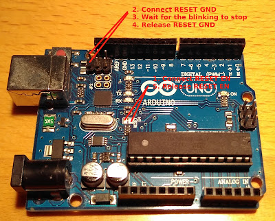
So Arduino Uno can introduce itself as a keyboard to a computer and send keystrokes to it. To do this we need to change the firmware of the ATmega16U2 chip. More on the theory here: https://www.arduino.cc/en/Hacking/DFUProgramming8U2

I'll just quickly summarize how I managed to do it.

First of all download Arduino-usbserial.hex Arduino-keyboard-0.3.hex from here: http://mitchtech.net/arduino-usb-hid-keyboard/

Connect your Arduino to the computer. Then connect the RESET EN points with a screwdriver, connect the RESET GND with a female-female wire, wait for the blinking to stop, release RESET GND, release RESET EN.
Now your ATmega16U2 is in bootloader mode (or something like that). Run the following commands from terminal:
sudo dfu-programmer atmega16u2 erase
sudo dfu-programmer atmega16u2 flash --debug 1 Arduino-usbserial-uno.hex

sudo dfu-programmer atmega16u2 reset
If the first command returns "dfu-programmer: no device present.", then either your Arduino is not in bootlader mode (disconnect/reconnect, do the RESET thing again), or your chip is not atmega16u2 (check what's written on it).

February 28, 2016

Hacking with ESP8266

I wasn't too active here in the last year, and the main reason is that I started a master in IT Security, and my projects became less electronics oriented. But now I had some time to play with my ESP8266 modules and try out some hacking with them. The module I'm using is named "NodeMcu Lua WIFI Internet Things development board based ESP8266 CP2102 module" on ebay and costs $5. I really like it, because it can be programmed with a normal USB cable, and it has all the connections easily accessible:

Creating a lot of fake access points

Technically it does not create any access points, but if you list the available access points with your phone or computer you will see a really a lot of them all with a random name and no encryption. The ESP8266 does it with sending beacon frames, similarly to the ones routers are using to advertise their wifi network. The original blogpost I was using is here: http://ruralhacker.blogspot.it/2016/01/esp8266-jamming.html and the code is here: https://github.com/kripthor/WiFiBeaconJam It was working for me flawlessly.

Disconnecting everyone from the wifi

There is a known attack against wifi networks: it is pretty easy to forge a deauth packet in the name of the access point and send it to the clients, and they will drop the connection (and usually try to reconnect). I was using this code from github: https://github.com/RandDruid/esp8266-deauth but it took me a while to make it work.
The problem is, that the developers of ESP8266 do not really want us to send these type of packages with the module. They (accidentally) added the functionality in SDK v1.3.0 but they removed it in v1.5.0. So we have to use v1.3.0. To do this with the Arduino IDE I did the followings:
  • I used a freshly downloaded Arduino 1.6.5
  • Then I added the staging version of esp8266 to Board Manager (more info: https://github.com/esp8266/Arduino)
  • I installed the ESP8266 boards version 2.1.0-rc2 from the Board Manager. The version is really important, because they use the SDK v1.3.0.
  • Then I edited the user-interface.h, because although the functionality is presented in the binaries of the SDK, it is not included in the header files. The user-interface.h was under ~/.arduino15/packages/esp8266/hardware/esp8266/2.0.0-rc2/tools/sdk/include/user_interface.h (I'm using Ubuntu).
    I simply added the following lines to the end of the file (before the #endif):
    typedef void (*freedom_outside_cb_t)(uint8 status);
    int wifi_register_send_pkt_freedom_cb(freedom_outside_cb_t cb);
    void wifi_unregister_send_pkt_freedom_cb(void);
    int wifi_send_pkt_freedom(uint8 *buf, int len, bool sys_seq);
Thereafter the code from github compiled fine, and it is working now. If it finds an access point and a client it notes it, and then it sends the deauth package to that specific host.
I have also tried to run the improved version using 2 ESP8266 module (https://github.com/RandDruid/esp8266-deauth2), but I couldn't make it work so far.

February 16, 2016

Setting up a random Chinese RGB led strip with Raspberry Pi using lirc

So I have ordered one of these RGB led strips from aliexpress:
It has an IR remote, but I wanted to integrate it into my home automation project. And so far it is going good.

First I installed lirc (Linux Infrared Remote Control) with using this tutorial: http://alexba.in/blog/2013/01/06/setting-up-lirc-on-the-raspberrypi/ I also had to update my firmware using this method: http://alexba.in/blog/2013/01/04/raspberrypi-quickstart/

The irrecord recorded the codes of the remote nicely, and now I can control it from command line.

I also installed lirc_web from here: https://github.com/alexbain/lirc_web I had some problems making it start automatically during boot (I was using this tutorial: http://alexba.in/blog/2013/11/02/lirc-web-nginx-and-upstart/). I had to change the line " exec /usr/local/bin/node /home/pi/lirc_web/app.js 2>&1 >> /var/log/open-source-universal-remote.upstart.log" to "exec /usr/bin/node /usr/local/lib/node_modules/lirc_web/app.js 2>&1 >> /var/log/open-source-universal-remote.upstart.log". Both the node folder and the app.js is in a different place.

Openhab

It wasn't running for me first, because some of its file was owned by root, and also the service has to be started by the openhab user. So here are the commands to solve this issue:
cd /etc/openhab (or where you installed it)
sudo chown -R openhab:openhab .
sudo su openhab -c 'service openhab start'

January 24, 2016

First steps with pilight

So I started to experiment with home automation, especially with pilight. Install went easily, but making it detect my devices was a bit harder (since I could not find any description on that). So I will write my experiences:
  1. The main config file is in /etc/pilight/config.json
  2. Connect your 433 MHz receiver and sender to the pins mentioned in the config file (default: sender - pin0, receiver - pin1). I have an extension board, so maybe the numbering will be different for you. Here is the mapping between the two numbering:

  3. pilight-receive - run it from command line, then press the button on your remote
  4. It will display a lot of possible decoding of your protocol. Try to find one, which you think is correct.
  5. Go to https://wiki.pilight.org/doku.php and search for your protocol to find an implementation with sample code. 
  6.  sudo service pilight stop; sudo nano config.json  - stop pilight and open config.json
  7. Copy the sample code to config.json and change according to the received values (usually change the id, unit etc.).
  8. Test it with: sudo service pilight start; sudo service pilight status
  9. If it says: "pilight failed to start" check the debug messages with sudo pilight-daemon -D   Probably there is an error in config.json. Fix it, and try again. 
  10. If it works, access the web interface under the port written in config.json.
  11. Try to change the value, or just see if it is changed by pressing the buttons on the remote
  12. If not, try an other result of pilight-receive
 And finally here is my config.json file with only a few entry (since plugA_old does not have a gui entry, it will not show up on the web interface):

{
        "devices": {
                "openDoor": {
                        "uuid": "0000-b8-27-eb-fd662e",
                        "protocol": [ "kaku_switch_old" ],
                        "id": [{
                                "id": 20,
                                "unit": 2
                        }],
                        "state": "off"
                },
                "plugA": {
                        "protocol": [ "kaku_switch" ],
                        "id": [{
                                "id": 2683906,
                                "unit": 0
                        }],
                        "state": "on"
                },
                "plugA_old": {
                        "protocol": [ "kaku_switch_old" ],
                        "id": [{
                                "id": 8,
                                "unit": 2
                        }],
                        "state": "off"
                }
        },
        "rules": {},
        "gui": {
                "openDoor": {
                        "name": "Door open sensor",
                        "group": [ "Living" ]
                },
                "plugA": {
                        "name": "Plug A - desk lamp",
                        "group": [ "Living" ]
                }
        },
        "settings": {
                "log-level": 6,
                "pid-file": "/var/run/pilight.pid",
                "log-file": "/var/log/pilight.log",
                "webserver-enable": 1,
                "webserver-root": "/usr/local/share/pilight/",
                "webserver-http-port": 5001,
                "webserver-cache": 1
        },
        "hardware": {
                "433gpio": {
                        "sender": 0,
                        "receiver": 1
                }
        },
        "registry": {
                 "pilight": {
                        "version": {
                                "current": "7.0"
                        }
                }
        }
}

January 21, 2016

ESP8266-based lasertag - alpha 0.1

So I have been working for a while on this project. My goal is to create a cheap lasertag solution, and they way I want to achieve it is to use ESP8266 modules communicating over wifi. Right now I'm in the middle of the development, but I have to order an other ESP8266 board, so I'm writing this article basically for me to be a reminder of what I did sofar. Although it might be useful for others too.

Here is my very first prototype:
As you can see I'm using an ESP8266-12 based development board with onboard voltage regulator and programmer, so I can program it via USB. I got it from ebay for $6.
I'm using the arduino ide to program it (for more see: https://github.com/esp8266/Arduino). For some reason the printed pin numbers on the board are not the same as I can access them from the code. So here is the mapping between the two:
Board - code
D1 - 5
D2 - 4
D3 - 0
D4 - 2
D5 - 14
D6 - 12
D7 - 13
D8 - 15
The board also has 2 built in led, a blue and a red available on pin 2 and 16 from the code.

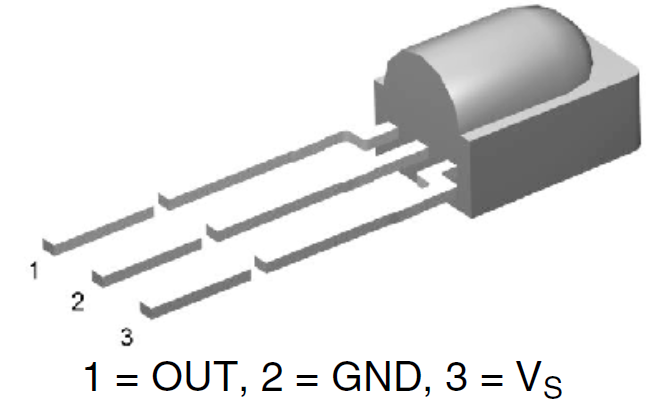
I have a red laser diode connected to pin D5/14, an IR receiver on D2/4 and a trigger with pull down resistor on pin D6/12. The IR receiver is connected this way:
The code uses the IRremoteESP8266 library, which was partly ported to ESP8266 by me and available here: https://github.com/markszabo/IRremoteESP8266 With this library it's easy to shoot and detect if got shot. However I want to add feedback also for the killer (like some sound from a piezo buzzer or similar). This feature is the main reason why I'm using ESP8266 and not simply arduino. So when the victim got hit, his gun will send a message to the killer, to notify him. To do this I chose a very easy solution: each gun is serving a webserver on port 80. The code, what the guns are sending through IR is the last 3 digits of their IP address. So when the victim receives a hit, it decodes the IR code, then sends a simple HTTP GET request to that IP like GET /?killed=123, where 123 is the last number of the victims IP address. It seems to work, but right now I have only one working ESP8266, so I could not test this feature

And here is the code (right now it's a bit "spaghetti code", in the end I will write it better):

#include <IRremoteESP8266.h>
#include <ESP8266WiFi.h>
#include <ESP8266WebServer.h>

//**************
//CONFIGURATION
//**************
//Pin config
int triggerPin = 12; //D6
int laserPin = 14; //D5
int receiverPin = 4; //D2
//Wifi config
const char* ssid = "MMaarrkk";
const char* password = "Iwilltellyoutomorrowat824";
//Misc config
int minimumTimeBetweenShoots = 500; //in millisecond

//Global variables

ESP8266WebServer server(80);

String lastNumberOfIP;

volatile int lastShootTime = 0;

IRrecv irrecv(receiverPin);
decode_results results;

IRsend irsend(laserPin);

int pin16state = false;
void killedSomeone() {
  // killedId = server.args(0);
  pin16state = !pin16state;
  digitalWrite(16, pin16state); //visualize it
  server.send(200, "text/plain", "1"); //answer with 1
}
void handleNotFound(){
  server.send(404, "text/plain", "404 error");
}

void setup() {
  Serial.begin(115200);
 
  irrecv.enableIRIn(); // Start the receiver
  irsend.begin();
  pinMode(triggerPin, INPUT);
  pinMode(16, OUTPUT);
 
  //connect to wifi
  WiFi.begin(ssid, password);
  Serial.println("");
  // Wait for connection
  while (WiFi.status() != WL_CONNECTED) {
    delay(500);
    Serial.print(".");
  }
  Serial.println("");
  Serial.print("Connected to ");
  Serial.println(ssid);
  Serial.print("IP address: ");
  Serial.println(WiFi.localIP());
 
  lastNumberOfIP = getLastNumberOfIP(WiFi.localIP().toString());
 
  //setup and start server
  server.on("/", killedSomeone);
  server.onNotFound(handleNotFound);
  server.begin();
}

void loop() {
  if (irrecv.decode(&results)) {
    Serial.print("Received value: ");
    Serial.println(results.value);
    hit(results.value);
    irrecv.resume(); // Receive the next value
  }
 
  server.handleClient();
 
  if(digitalRead(triggerPin)) shoot();
  delay(100);

}

void shoot()
{
  if(lastShootTime+500 < millis()){
    Serial.println("Shooting");
    lastShootTime = millis();
    irsend.sendNEC(lastNumberOfIP.toInt(), 36);
    //irrecv.resume();
  }
}

void hit(int killer)
{
  // Use WiFiClient class to create TCP connections
  WiFiClient client;
  //const char* chKiller = "000";
  //String(killer).toCharArray(chKiller,3);
  //const char* host = "192.168.0." + String(killer);
  String host = "192.168.0." + String(killer);
  const int httpPort = 80;
  if (!client.connect(host.c_str(), httpPort)) { //host: String -> const char * with c_str()
    Serial.println("connection failed");
    return;
  }
 
  // We now create a URI for the request
  String url = "?killed=" + lastNumberOfIP;
 
  Serial.print("Requesting URL: ");
  Serial.println(url);
 
  // This will send the request to the server
  client.print(String("GET ") + url + " HTTP/1.1\r\n" +
               "Host: " + host + "\r\n" +
               "Connection: close\r\n\r\n");
  delay(10);
  /*
  // Read all the lines of the reply from server and print them to Serial
  while(client.available()){
    String line = client.readStringUntil('\r');
    Serial.print(line);
  }*/
}

String getLastNumberOfIP(String ip)
{
  return ip.substring(ip.lastIndexOf('.')+1);
}