December 25, 2014

Getting started with ESP8266 Wifi module

Introduction

I ordered an FT232RL USB To Serial Adapter Module and an Arduino Pro Mini (Atmega328 3.3V 8MHz) in a kit for $7 and an ESP8266 Serial Wifi Module for $3.21 in the hope of getting a Wifi capable small Arduino for as cheap as $10. I got those modules last week and already wrote a post about the Arduino Pro Mini, and now I got the wifi module also working.

Communicating with ESP8266 Wifi module directly (with gtkterm)

Wiring

I connected the ESP8266 with the FT232RL USB To Serial module accortding to the following description: http://rayshobby.net/?p=9734 . The pinout of the module:
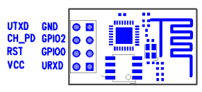
"Connect the top two pins (UTXD, GND) and bottom two pins (VCC, URXD) to the RXD, GND, VCC, TXD pins of a microcontroller. Note that VCC must be no more than 3.6V. The middle four pins are should be pulled up to VCC for normal operation. However, if you need to upgrade the firmware of the module, you need to pull the GPIO0 pin to ground — that way upon booting ESP8266 will wait for a new firmware to be uploaded through serial. This is how you can upgrade the firmware in the future." (Source of the pinout and text: http://rayshobby.net/?p=9734 )

Communicating using gtkterm

After the physical connection it took me a while to figure out how to communicate with the module. First of all it can be called with AT codes (nice collection here: https://nurdspace.nl/ESP8266#AT_Commands), so I just needed to send those commands to the module in serial port. I am using Ubuntu, so I found gtkterm as a program for serial communication. After installing it with sudo apt-get install gtkterm and looking in the manual I thought it would be easy. I found out the serial port number for FT232RL using an ls /dev/ before and after connecting the device, and found the port /dev/serial/by-id/usb-FTDI_FT232R_USB_UART_A9M55VZZ-if00-port0. I also needed the baudrate of the communication. I found on many websites that it is 115200 or 57600, but mine was using 9600 (took me a while to figure out). So the final command for gtkterm was this:
gtkterm -p /dev/serial/by-id/usb-FTDI_FT232R_USB_UART_A9M55VZZ-if00-port0 -s 9600 
After entering this command gtkterm should open in a different window. But there is a problem: ESP8266 and gtkterm use different end-of-line characters, so I got no respond after typing in any command and pressing enter. The solution was to define a macro for Shift+Enter, which would send the text \0D\0A, which is equal to \r\n:
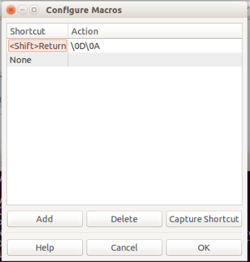
After defining this macro the AT commands worked like charm, I only needed to press Shift+Enter in the end of every command. I could list the available wifi networks, connects to the chosen one and so on. Nice description was found here: http://www.electrodragon.com/w/Wi07c#Steps_and_note

Updating firmware

First of all this action requires to change the wiring and connect GPIO0 pin to ground. I used the esptool.py software (can be downloaded from here) and the newest firmware for ESP8266 from here. The command was figured out using the readme file of esptool.py on its github page:
./esptool.py -p /dev/serial/by-id/usb-FTDI_FT232R_USB_UART_A9M55VZZ-if00-port0 write_flash 0x000000 v0.9.2.2ATFirmware.bin
It took a while to update the firmware but worked without a problem.

Using with Arduino

First of all the ESP8266 works on 3.3V so a normal Arduino with 5V logic will destroy it. That's why I used an Arduino Mini Pro with 3.3V logic. The usage is not too hard, basically just like a normal serial communication. The Arduino sends AT commands and receives the same responses as we did with direct connection. 
Using this intructable I wrote a program to send the analog value of port A0 to ThingSpeak.com in every 5 second. It was pretty straight forward using the instructable, so I won't write to much about it.

Wiring

The code


#define SSID "my_wifi_ssid"
#define PASS "my_wifi_password"
#define IP "184.106.153.149" // thingspeak.com
String GET = "GET /update?key=[THINGSPEAK_KEY]&field1=";


void setup()
{
  Serial.begin(9600);
  Serial.println("AT");
  delay(5000);
  if(Serial.find("OK")){
    connectWiFi();
  }
}

void loop(){
  String a=String(analogRead(A0));
  update(a);
  delay(5000);
}

void update(String analog){
  String cmd = "AT+CIPSTART=\"TCP\",\"";
  cmd += IP;
  cmd += "\",80";
  Serial.println(cmd);
  delay(2000);
  if(Serial.find("Error")){
    return;
  }
  cmd = GET;
  cmd += analog;
  cmd += "\r\n";
  Serial.print("AT+CIPSEND=");
  Serial.println(cmd.length());
  if(Serial.find(">")){
    Serial.print(cmd);
  }else{
    Serial.println("AT+CIPCLOSE");
  }
}


boolean connectWiFi(){
  Serial.println("AT+CWMODE=1");
  delay(2000);
  String cmd="AT+CWJAP=\"";
  cmd+=SSID;
  cmd+="\",\"";
  cmd+=PASS;
  cmd+="\"";
  Serial.println(cmd);
  delay(5000);
  if(Serial.find("OK")){
    return true;
  }else{
    return false;
  }
}

Result

It was working as it intended to:

Controlling the Arduino from the web

So I was be able to send data to a website. Would it be possible, to do it in the opposite direction and turn on and off an led from a website? I started to do this, and after the Arduino send the GET command it receives the website sourcecode, but also the header of the site, like i found here
AT+CIPSEND=0,47

>
 GET / HTTP/1.1
Host: retro.hackaday.com:80


busy

busy

SEND OK


+IPD,0,1024:HTTP/1.1 200 OK
Server: nginx/1.6.2
Date: Fri, 26 Sep 2014 20:27:11 GMT
Content-Type: text/html
Content-Length: 13258
Connection: keep-alive
Last-Modified: Fri, 26 Sep 2014 20:00:10 GMT
Accept-Ranges: bytes

<html>
<head>
<title>Hack a day</title>
</head>
<body>
code of the site
</body>
</html>
First I thought I would only get the sourcecode, and wrote my software that way, but that didn't work because of the header, and I haven't got time yet to fix it, so I will do that later.

Conclusion

For $10 I got a working Arduino with a wifi module, capable to connect to wifi networks and open webpages, which is amazing and I can't wait to use it in a real (useful) project like a lasertag system or some sort of home automation.

Best regards and merry Christmas:
Mark

December 18, 2014

How to upload code to Arduino Pro Mini 3.3V with FT232RL USB To Serial Adapter

Introduction

So yesterday I got my tiniest Arduino, an Arduino Pro Mini 3.3V 8Mhz based on Atmega328. It is only 18x33 mm, so really tiny compared to Uno:

As you can see it doesn't has any usb connector, so I also ordered an FT232RL USB To Serial Adapter to be able to program it. It's available on ebay in kit with the Pro Mini only for $7 with free shipping. That sounded cool, but after I received it I  realized what the Pro stands for: I just couldn't find any step by step guide about how to connect the Arduino with the FT232RL.
An other important detail: there is two version of Arduino Pro Mini. One has a 16 Mhz processor and operates on 5V like the normal Arduino UNO, the other one has a 8 MHz processor and operates on 3.3V. I got the second one, because I want to use it with a cheap Wifi modul (ESP8266), which operates on 3.3V.

Wiring

Fist of all the FT232RL has a solder pad to change the power supply between 3.3V and 5V. The first step have to be to change it to 3.3V, otherwise the Pro Mini can be damaged!
After changing to 3.3V, the wiring is easy as seen in the following picture:

Programming

It's pretty similar to the other Arduinos, just start the Arduino software, select board type (in my case: Arduino Pro or Pro Mini (3.3V 8MHz) w/ ATmega328) and upload the code. I first uploaded the classical Blink program, and it runs without a modification (first I was unsure if it also has a build in led on pin 13, but it does and it blinks like charm).

Conclusion

It is easy to use this small Arduino, I'm looking forward to use it projects where size matters. I have plans about an Arduino based lasertag system and home automation projects, where with the ESP8266 wifi module it can be a cheap and powerful combination. 
Btw you should use female-female cables or usb extension cable to avoid solutions like mine:

September 02, 2014

RaspberryPi Remote Control Robot with Camera

Introduction

I already made a remote control car using arduino in my previous project. Now I improved it a bit, added a raspberry pi with camera and wifi dongle, so I had live video and the ability to control it over wifi instead of bluetooth. So here is the result:

Part 1 - Hardware and arduino code

It's 95% the same as in my previous project: http://nomartini-noparty.blogspot.hu/2014/01/bluetooth-remote-control-car-2wd.html The only difference is that now I don't need a bluetooth modul or any battery, the arduino is connected to the raspberry pi via a simple usb cable. It handles the serial communication and also gives enough power for the microcontroller and the motors (H-Bridge power pins are connected to Vin and GND on arduino).

Part 2 - Raspberry Pi, remote control

Let's start with a raspberry pi running raspbian. First I configured wifi as written on this tutorial. Then I installed apache, vsftpd and php as written here. Also tornado for the sockets need to be installed with the commands: sudo apt-get install python-pip and pip install tornado. Then I edited BrowserBot by Dexter Industries and came to this:
  • Replace /var/www/index.html with this file. It is basically the BrowserBot Client Code, the only change I made was to replace
    <input id="touch" style="height: 100px; width: 100px; position: absolute; left: 550px; top: 100px" type="button" value="Accelerate" onclick="accelerate(); " />
    with
    <input id="touch" style="height: 100px; width: 100px; position: absolute; left: 550px; top: 100px" type="button" value="Accelerate" onmousedown="accelerate(); " onmouseup="stop(); " />
    for every button. So with this change the car will go only forward as long as you press the button and instantly stops if you release.
    What this website actually does, opens a socket and send a character to the pi when a button is pressed.
  • On the raspberry side we need to handle the socket. For this task this file need to be run. This is an edition of browserBot server code I removed/commented out the code drived the LEGO Robot and added the following lines:
    to the beginning of the file:
    import serial
    import time
    global ser

    under  if __name__ == "__main__":
    ser = serial.Serial('/dev/ttyACM0', 9600)
    and under WSHandler
def on_message(self, message):      # receives the data from the webpage and is stored in the variable message
print 'received:', message        # prints the revived from the webpage 
if message == "u":                # up
 ser.write('F')
 print 'F sent to arduino'
elif message == "d": #down
 ser.write('B')
 print 'B sent to arduino'
elif message == "l": #left
 ser.write('L')
 print 'L sent to arduino'
elif message == "r": #right
 ser.write('R')
 print 'R sent to arduino'
elif message == "b": #middle
 ser.write('S')
 print 'S sent to arduino'
def on_close(self):
print 'connection closed...'
Now if you run python arduino_server.py your raspberry will wait for command coming through the socket, and if comes, it sends the corresponding data to the arduino through serial port. For opening the socket on client side you only need to be on the same network as your pi and enter your pi-s ip address on the browser. If apache is correctly configured and running you should see the control site. Don't forget to fill in the ip address box with your pi-s ip, otherwise the socket will not work!

Part 3 - Video stream

First I tried various web based solutions, like motion and ustream but the lag was always too long to control the car real time. So I searched for lagless video stream on raspberry pi and ended up with this article. Which is quite good, but sadly use a raspberry cam and Mac. So after some research I ended up with the following code (after installing gstreamer1.0 on pi and my ubuntu):
  • first run on ubuntu: gst-launch-1.0 -v udpsrc port=5001 caps="application/x-rtp, media=(string)video, clock-rate=(int)90000, encoding-name=(string)H264" ! rtph264depay ! avdec_h264 ! videoconvert ! autovideosink sync=false
  • then run on pi: gst-launch-1.0 -v -e v4l2src device=/dev/video0 ! 'video/x-raw,format=I420,width=640,height=480,framerate=30/1' ! omxh264enc target-bitrate=6500000 control-rate=variable ! rtph264pay pt=96 ! udpsink host=192.168.1.103 port=5001
(The red ip is the ip of my computer running ubuntu). A new window should appear on ubuntu showing the image of the webcam as seen on the first video.

Summary

So that's it, there is a lot to develop on this project, but I had only one day and don't know when will I be able to continue, so it was good to write down what I did. And if I could help someone, I'm happy to do so. If you have any question or comment, please feel free to write.

Best regards:

Mark

January 08, 2014

Bluetooth remote control car - 2WD

Introduction

Half year ago I made a remote control car with my roommate. It was made of a non-working RC-car, so now I built it from scratch, only using things which everyone can buy. I want to make it as a tutorial for beginner, so feel free to make it as your first arduino project.

What you need:

  • arduino (if you don't have one, buy an arduino uno from ebay, from dx or from the original seller) - $17 (I've used arduino mega, but uno would do the same)
  • 2WD Robot Raider Car Kits for Arduino from dx - $23
  • bluetooth modul. I've used a JYMCU from ebay - $3.5
  • a H-Bridge to drive the motors. I've used L9110S from ebay - $2
  • battery holder from dx  $2.5
  • breadboard and a couple of wire - $2
Sum: $50
And what you got for this money:

Hardware

First build up the car chassis. I think, it's pretty obvious. It comes with 2 DC motors.

H-Bridge

H-Bridge is responsible for driving the motor back and forth. It's also usefull, because gives us the ability to use different powersource (aka batteries) for the motors and the arduino. It's necessary, because otherwise when the motors start, they take so much power from the arduino than it drops the bluetooth connection. To learn more about H-Bridge, see Wikipedia.
Wiring it: it's pretty simple. Just connect one motor to motor A and the other to motor B. On the other side of the IC there are 6 connectors for the power and control. Connect GND and VCC with a breadboard to the battery for the motor, and the other 4 to the arduino pins 8-11. Like this:

Bluetooth modul

Connect the BT modul to pin 0 and 1 so, that BT's RX pin is connected to arduino TX pin (pin 1) and BT's TX to arduino's RX (pin 0). But be careful! If you connect the arduino TX and RX pin it won't get any further data from the USB cable, so connect those pins only after upload your code! 
Also connect VCC to 3.3V and GND to GND on arduino. It should work with 5V too.

Now add power source for the arduino and put on the cover

Arduino code

Smartphone part

Just download this app from Google Play, and it will work. When connecting to the car choose the bluetooth device with the name linvor. If it asks for code, use 1234.

I hope this tutorial could help you. If anything unclear, feel free to comment.

Best regards:
Mark